CSI, IQ Capture, and Research Features
Because the PHY is open and the platform can receive its own transmissions (full duplex), openwifi gives you instrumentation that no commercial Wi-Fi chip exposes.
One side channel for two data types
CSI and IQ capture share the side channel infrastructure. The FPGA side_ch module collects data and DMAs it to the processor, while side_ch.ko and side_ch_ctl move it to your PC for analysis in Python or MATLAB. See FPGA IP Cores → side_ch for the FPGA tap points.
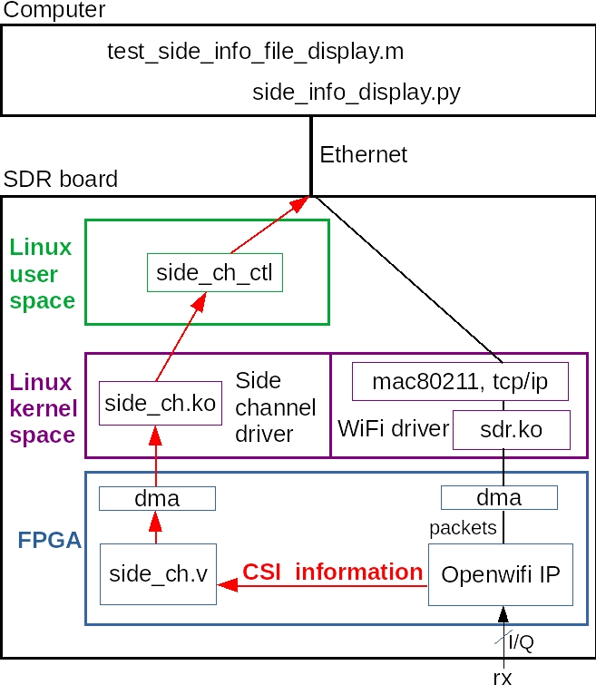
The side-channel data path: side_ch captures data and DMAs it to the board's processor, then side_ch_ctl forwards it over UDP (port 4000) to a display and analysis script on your PC.
Before using these recipes on a board updated beyond the default SD image, follow Building to rebuild side_ch_ctl and, when needed, side_ch.ko. The side_ch_ctl and the Side Channel page is the reference for its command syntax, module parameters, register map, trigger conditions, and capture troubleshooting.
Everything below works in monitor mode and also alongside live AP, client, or ad-hoc operation. Bring the link up first, then start the side channel.
CSI (Channel State Information)
openwifi extends "CSI" from Channel State Information to Chip State Information. For each packet, you can pull the timestamp, frequency offset, channel response, and equalizer output up to your PC.
Quick start
# on the board:
cd openwifi
./wgd.sh
./monitor_ch.sh sdr0 11        # monitor a busy channel
insmod side_ch.ko
./side_ch_ctl g
If the printed "side info count" keeps climbing, CSI is flowing. Then, on the PC (not over ssh):
cd openwifi/user_space/side_ch_ctl_src
python3 side_info_display.py     # needs python3-numpy, python3-matplotlib, python3-tk
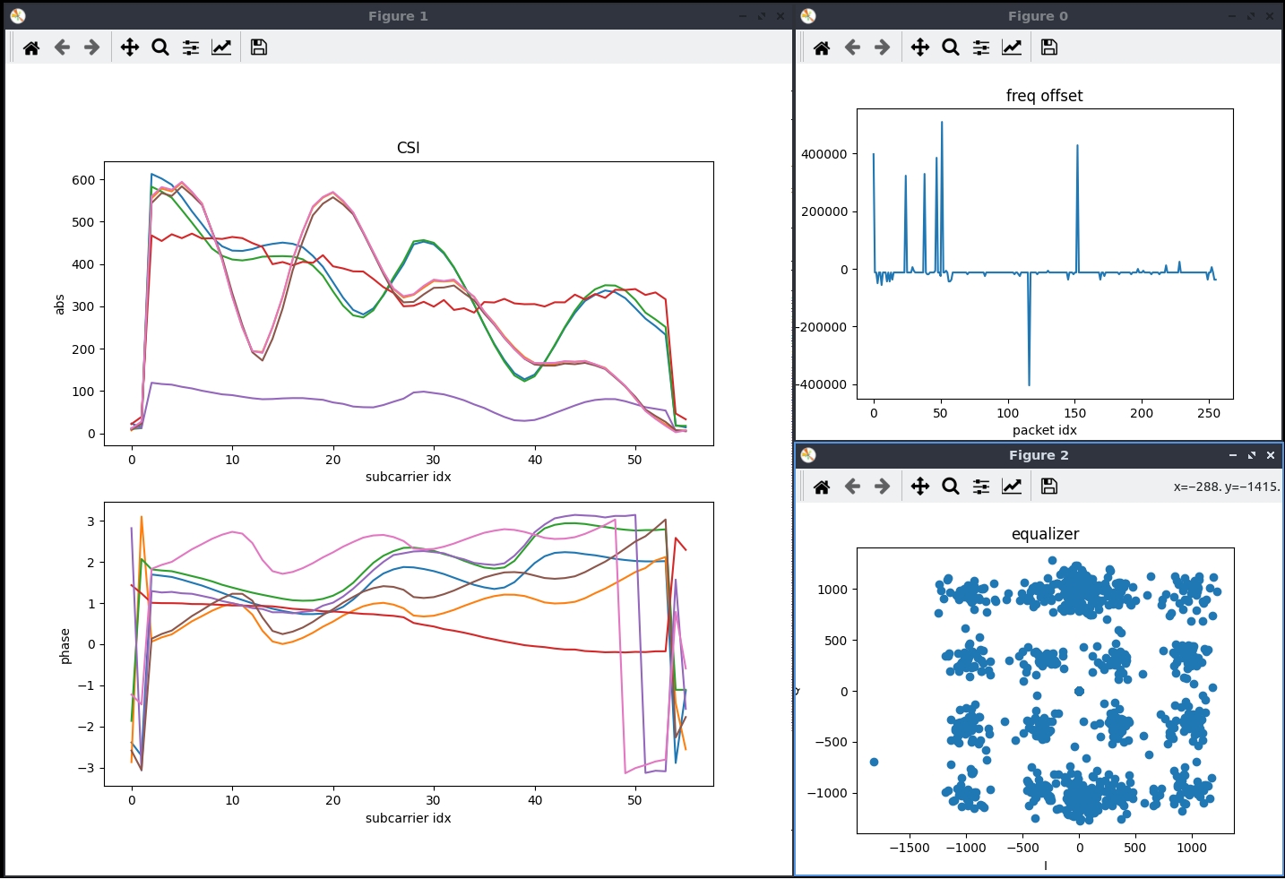
You'll get live plots of frequency offset, channel response, and the equalizer constellation, with the timestamp printed. Everything is also logged to side_info.txt for offline work with the MATLAB script test_side_info_file_display.m.
Data format
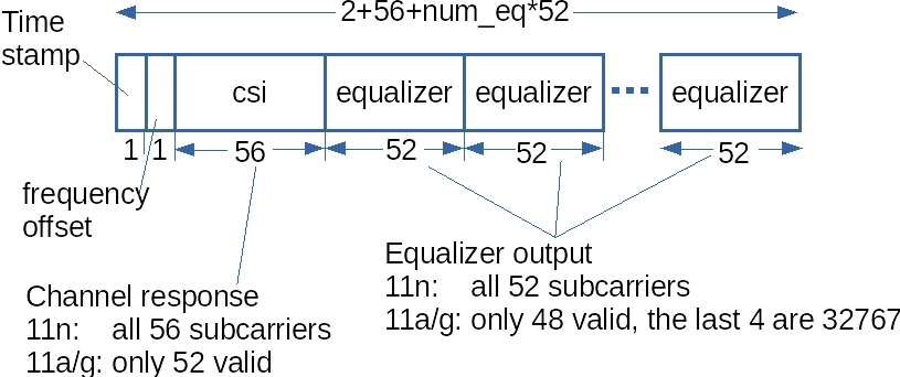
Each element is 64-bit:
- a 64-bit TSF timestamp, identical to the value shown by tcpdump and Wireshark, so you can map CSI to packets
- freq_offset (first 16 bits used)
- csi and equalizer (first two 16-bit words used for I/Q of the channel response and equalizer output, the rest reserved for future multi-antenna use)
The Python and MATLAB scripts are the precise reference for parsing.
Capturing only specific packets
By default you get CSI for every decoded packet. To filter by Frame Control, addr1 (target), or addr2 (source), configure register 1 before g. Bits of the value: 001 in the low 12 bits enables the feature, bit 12 = FC match, bit 13 = addr1 match, bit 14 = addr2 match.
# Capture only packets from source MAC 56:5b:01:ec:e2:8f:
./side_ch_ctl wh1h4001          # enable addr2 (source) match
./side_ch_ctl wh7h01ece28f      # target addr2 = last 32 bits of the MAC
./side_ch_ctl g
Set the match targets with wh5h<FC> (Frame Control), wh6h<addr1>, wh7h<addr2>. Only the last 32 bits of a MAC are needed.
num_eq (equalizer outputs)
Reduce how many equalizer outputs you capture (valid 0 to 8, default 8). Keep the value aligned across all three tools:
insmod side_ch.ko num_eq_init=3
python3 side_info_display.py 3      # and set num_eq=3 in the MATLAB script
CSI radar (full-duplex self-sensing)
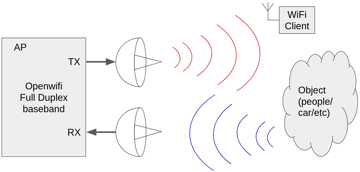
openwifi's baseband can receive its own transmit signal. With a TX and an RX antenna (ideally two directional antennas facing the scene), its CSI reflects changes in the environment. This enables joint radar and communication on a Wi-Fi platform. Read the normal CSI section before following this recipe.
Unlike the other recipes on this page, this one runs from the reloadable driver and FPGA package, drv_and_fpga.tar.gz, unpacked into drv_and_fpga/. It does not use the preinstalled files under /root/openwifi (see Reloading driver and FPGA without rebooting). Rebuild side_ch_ctl first by following Building.
Bring up the driver and FPGA package, monitor a channel, restrict CSI to your injector's source MAC, and unmute self-reception. Then inject packets to sound the channel:
# on the board, after loading drv_and_fpga.tar.gz and monitoring channel 1:
insmod ./drv_and_fpga/side_ch.ko
./side_ch_ctl wh1h4001
./side_ch_ctl wh7h4433225a          # only CSI from XX:XX:44:33:22:5a (our injector)
./sdrctl dev sdr0 set reg xpu 1 1   # UNMUTE baseband self-receive
./side_ch_ctl g0

# in a second ssh session, inject continuously:
cd /root/openwifi/inject_80211 && make
./inject_80211 -m g -r 4 -t d -e 0 -b 5a -n 99999999 -s 20 -d 1000 sdr0
# (802.11n variant: -m n -r 4 -t d -e 8 -b 5a ...)
Then on the PC, python3 side_info_display.py 8 waterfall shows CSI, a CSI waterfall, equalizer output, and frequency offset. The waterfall visibly changes as objects or people move between the antennas. Data logs to side_info.txt for offline analysis. The key control is xpu register 1 (xpu 1 1 unmutes self-RX).
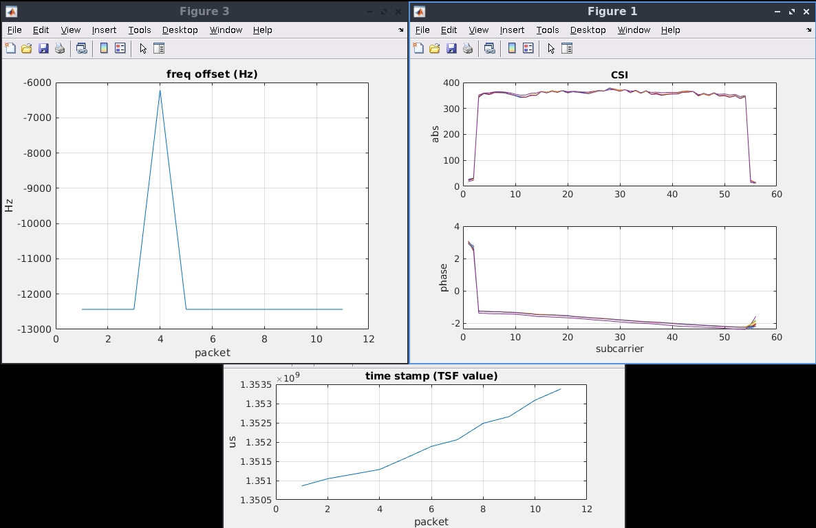
Offline CSI-radar analysis. The waterfall plot shows the channel response changing over time as a person moves between the two directional antennas.
CSI fuzzer (privacy protection)
Wi-Fi CSI can be used to sense people and activity passively and without consent (keystrokes, presence, motion). The CSI fuzzer counters this by injecting a controlled artificial channel response into the transmitter, so an eavesdropper's CSI-based sensing is corrupted while normal communication continues. It is backed by peer-reviewed work (ACM WiSec 2021 and a privacy-protection paper).
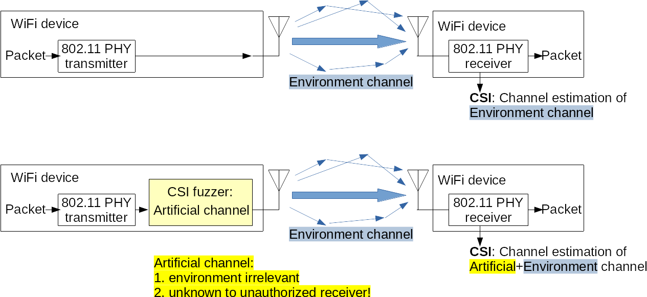
The fuzzer's principle, with the artificial CSI applied at the transmitter so it mixes with the real channel:
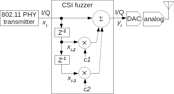
Full duplex lets you watch the artificial CSI you're creating via the same self-monitoring setup. First set up CSI self-monitoring as in CSI radar, then in another ssh session:
cd openwifi
./csi_fuzzer_scan.sh 1     # sweep artificial-CSI values (calls csi_fuzzer.sh)
The self-monitored CSI changes visibly. csi_fuzzer.sh 1 45 0 13 applies one specific artificial response. Its four arguments describe a two-tap filter, c1_rot90_en c1_raw c2_rot90_en c2_raw, with each raw value from -64 to 63, packed into tx_intf register 5. csi_fuzzer_scan.sh {1|2|3|4} sweeps tap1, tap2, or their combinations across the full range by calling csi_fuzzer.sh repeatedly.
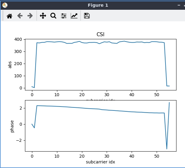
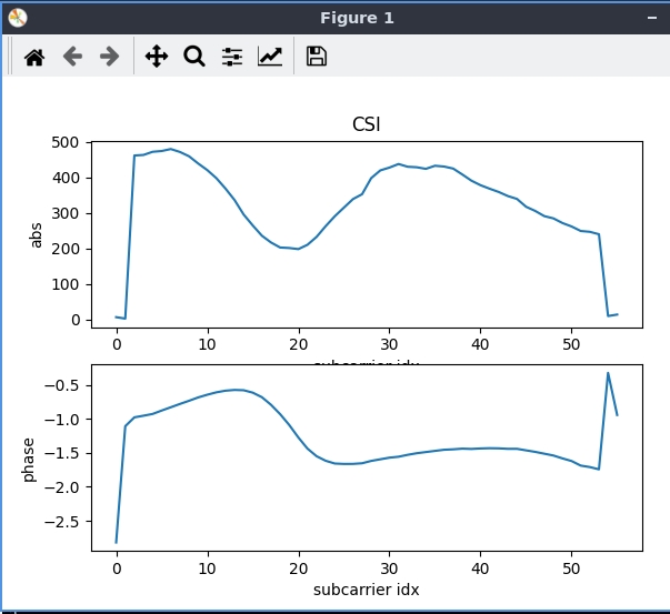
Self-monitored beacon CSI before (left) and after (right) applying ./csi_fuzzer.sh 1 45 0 13. The injected artificial response visibly reshapes the channel an eavesdropper would measure.
IQ capture
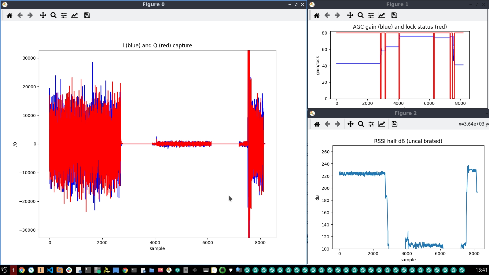
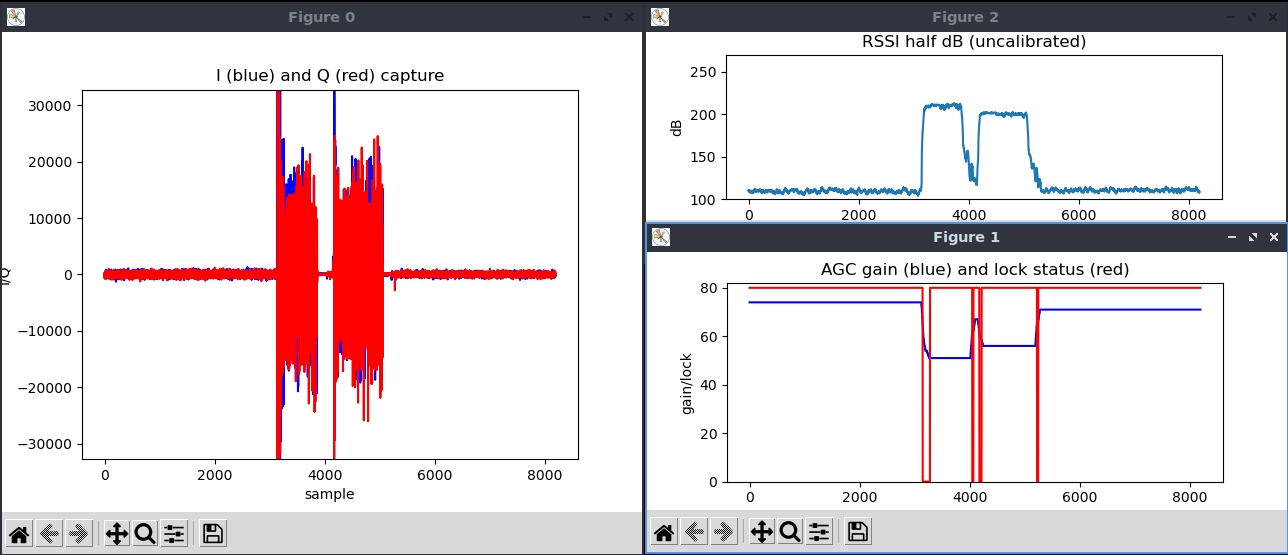
Capture raw baseband IQ samples, plus AD9361 AGC gain and lock status, RSSI, and a comparison of FPGA-estimated vs. Python-computed frequency offset.
Quick start
# on the board:
./wgd.sh
./monitor_ch.sh sdr0 11
insmod side_ch.ko iq_len_init=8187      # small FPGA (Zynq-7020): use <4096, e.g. 4095
./side_ch_ctl wh3h01                    # switch the core to IQ mode
./side_ch_ctl wh11d4094                 # only needed on small-FPGA (Zynq-7020) boards
./side_ch_ctl g
That captures IQ received off the air, which is register 5's default. Register 3 selects the mode, not where the IQ is tapped from. To capture your own transmit instead, set the source in register 5 (see the register map).
Rising "side info count" means triggers are firing. Then on the PC:
cd openwifi/user_space/side_ch_ctl_src
python3 iq_capture.py                    # small FPGA: pass the iq_len, e.g. 4095
You'll see live IQ, AGC gain + lock status, and uncalibrated RSSI, with the timestamp printed. Data logs to iq.txt for test_iq_file_display.m (set iq_len to match in the MATLAB script).
Format
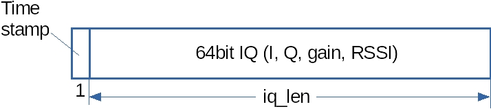
A 64-bit TSF timestamp records when the trigger fired. Each 64-bit sample contains:
- two 16-bit words of I/Q from the active antenna
- one 16-bit word of AD9361 AGC gain (bit7 = lock status, bits6-0 = gain)
- one 16-bit word of uncalibrated RSSI (half-dB)
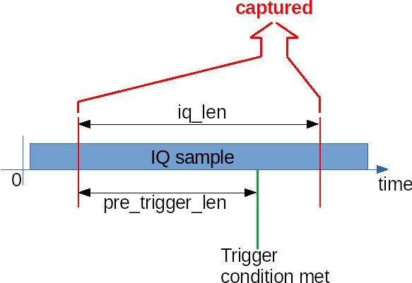
The capture is windowed around a trigger event: iq_len total samples, of which pre_trigger_len come before the trigger.
iq_len and pre_trigger_len
iq_len= samples captured per trigger. Set once at insert time:insmod side_ch.ko iq_len_init=3000(valid 1 to 8187, small FPGA 1 to 4095). You must specifyiq_len_initto enable IQ mode, because insertingside_ch.kowith no parameter runs CSI mode instead. Keep the value aligned acrossside_ch.ko,iq_capture.py, and the MATLAB script.pre_trigger_len= how many samples before the trigger are included:./side_ch_ctl wh11dY(valid 0 to 8190, small FPGA 0 to 4094).
Trigger conditions (register 8)
./side_ch_ctl wh8dY selects the trigger (0 to 31). These triggers appear in the recipes below:
| Y | Trigger |
|---|---|
| 0 | FCS checked (pass or fail), or free-run when register 5 bit 0 is set |
| 8 | Long preamble detected |
| 16 | tx_control_state hits the target set in register 5 |
| 23 | TX finishes for a packet that needs an ACK |
| 25 | Address match, subject to the match bits in register 1 |
| 29 | Antenna 1 IQ exceeds the threshold while TX RF is ongoing |
For free-run, use wh8d0 and wh5d1 together. The full trigger reference covers all 32 conditions. See the register configuration for thresholds and register 5 settings.
Frequency-offset check and SNR
iq_capture_freq_offset.pyprints FPGA-estimated vs. Python-computed frequency offset. If they diverge, override the FPGA estimate withreceiver_phase_offset_override.sh. (ChangeLUT_SIZEin the script when testing 802.11ax.) The example in the IQ app note usesiq_len_init=1500on a clean channel. It triggers on either an addr1 and addr2 match (trigger 25) or "long preamble detected" (trigger 8).show_iq_snr.mcomputes SNR from a captured.matfile: runshow_iq_snr(mat_file)to eyeball the RSSI mid-point, thenshow_iq_snr(mat_file, middle_value)to get the number. Do this with a single clean signal source (for example cable test) for meaningful results.
Dual-antenna IQ (collision capture)
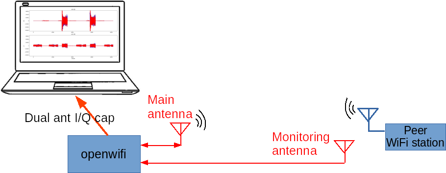
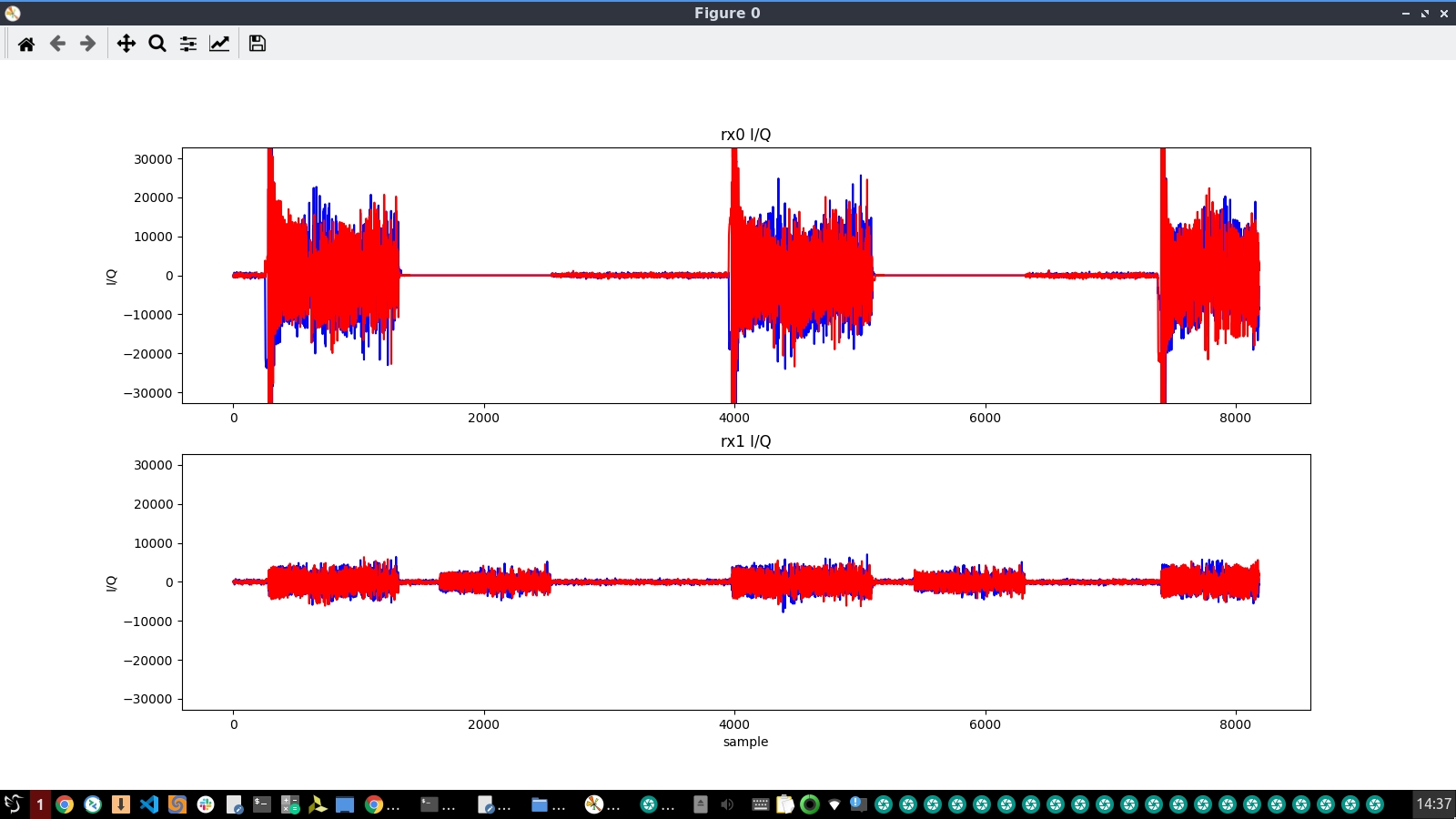
On AD9361 boards (FMCOMMS2/3, ADRV9361-Z7035) you can capture IQ from the monitoring antenna (rx1) coherently alongside the main antenna (rx0). Place rx1 near a peer node to catch collisions, which happen when both ends of a link transmit at once.
First set rx1's AGC to manual at a low gain in rf_init.sh, with echo manual > in_voltage1_gain_control_mode and echo 20 > in_voltage1_hardwaregain. The script runs these in the AD9361's /sys/bus/iio/devices/iio:deviceN/ directory, which it finds by scanning iio:device0 through iio:device4. Then use a short pre_trigger_len and a TX-done trigger (wh8d23). You can also use the dedicated collision trigger wh8d29, which fires when rx1 IQ is above a threshold while this SDR is transmitting. Capture with iq_capture_2ant.py. The full recipe is in the dual-antenna IQ note.
The same note has two more quick starts that capture the board's own TX IQ from inside the FPGA instead of anything received over the air. The first uses trigger 16, a tx_control_state match (see the trigger reference). Set wh8d16, then wh5h2 to tap the IQ at the openofdm_tx core or wh5h4 to tap it at tx_intf. The upstream note describes this combination as firing when the transmitter starts, while the RTL defines trigger 16 as a control-state hit with the target state set by wh5. The second is a free-running mode that streams transmit baseband continuously (wh8d0 with source wh5h3 or wh5h5). Both use a short capture window (iq_len_init=511, enough for the preambles and a few OFDM symbols) and the same iq_capture_2ant.py display.
ACK timing measurement
You can trigger IQ capture on the ACK-send event, which lets you measure ACK timing directly. The Rx-ACK-GAP and Tx-ACK-GAP should both sit around a 16 µs SIFS. Keep the receiver always on (xpu 1 1) and configure wh3h21 for the right IQ composition. Set the trigger with wh5h20 and wh8d16, and capture with g0. Generate traffic (for example a ping sweep of payload sizes across all MCS from a second board), then analyze offline with test_iq_file_ack_timing_display.m. See the ACK-timing note.
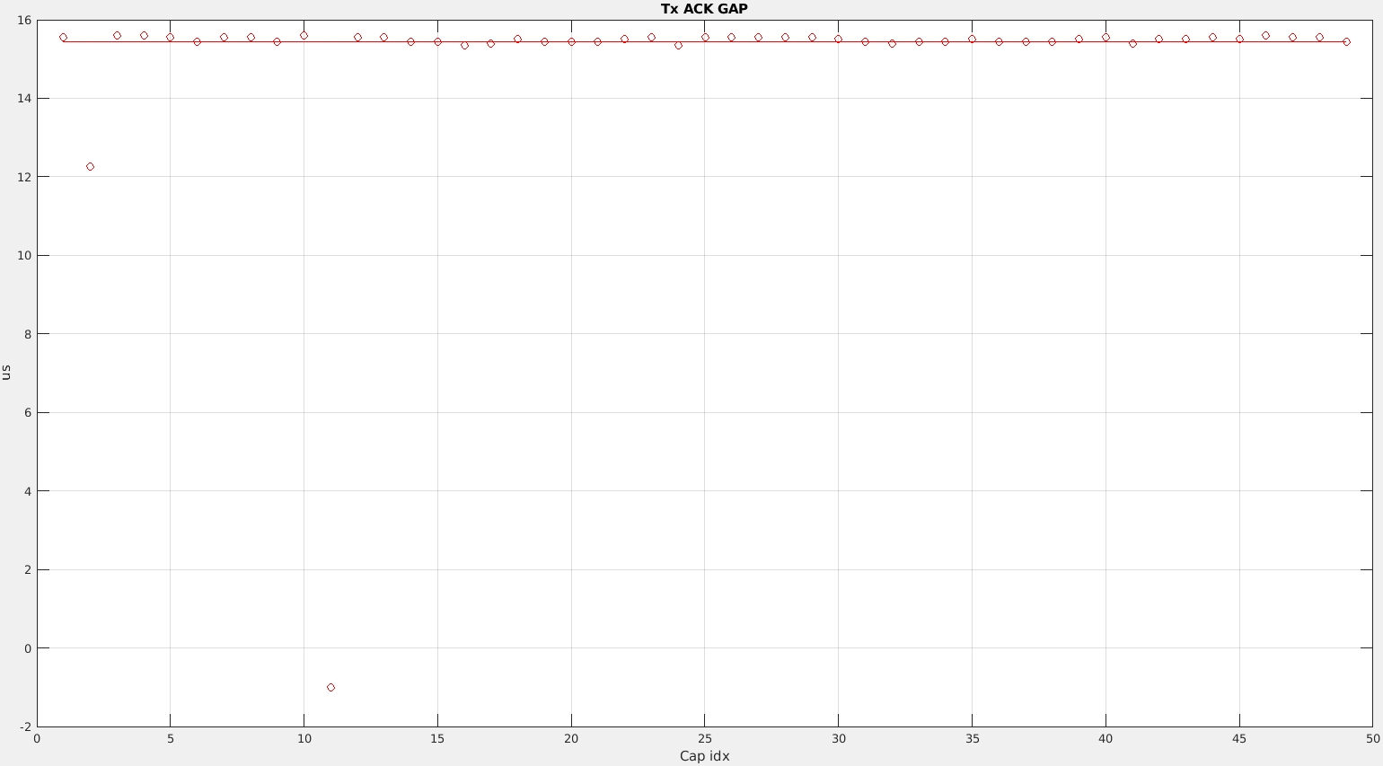
This technique is precise enough to have caught real bugs. The plot below shows abnormal Tx-ACK-GAPs, a gap of about 12 µs and a "-1" no-event. They were caused by AGC-induced DC power before the ACK, which was mis-detected as the start of the ACK. This bug has since been fixed.
Self-loopback testing
Full duplex also enables self-loopback tests of packets, CSI, and IQ, either over the air (TX and RX antennas close together) or entirely inside the FPGA. This is a good way to verify the transmitter and receiver without a second node.
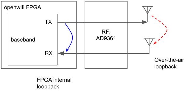
The test needs these settings:
- monitor mode
- CCA effectively disabled with
./sdrctl dev sdr0 set reg xpu 8 1000, a threshold above any real signal level, so the channel always reads idle - self-RX unmuted (
xpu 1 1) - a TX-control-state trigger (
wh8d16, trigger 16 above) - the loopback source select,
side_ch_ctl wh5h0for over the air orwh5h4for FPGA-internal
Inject a packet in a second ssh session (./inject_80211 -m n -r 5 -n 1 sdr0) to fire the capture.
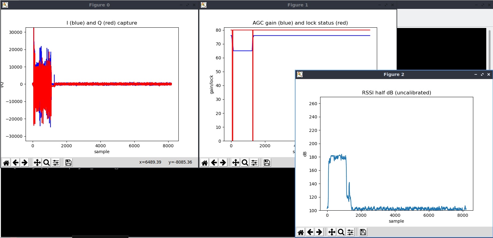
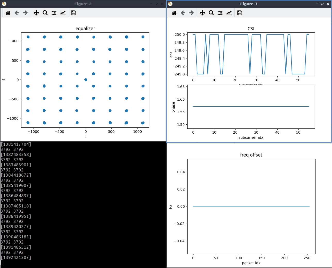
Left: IQ captured from an over-the-air self-loopback packet. Right: CSI and constellation over the ideal FPGA-internal loopback channel. It is useful as a "golden" reference, since it has no real-channel distortion.
The loopback note has the full walkthrough.
Counters and statistics
Driver-level (sysfs)
Per-packet TX and RX counters are on the sdrctl page: stat_enable.sh, tx_stat_show.sh, rx_stat_show.sh (with PER calculation), tx_prio_queue_show.sh, rx_gain_show.sh, per-peer filtering, and ACK inclusion.
FPGA event counters
Two additional counter sources live in the FPGA:
openofdm_rx watchdog counters: the signal_watchdog inside openofdm_rx detects abnormal signals early so the receiver does not spend time decoding them. Select an event with sdrctl dev sdr0 set reg rx 17 <type>. The types are 0 (phase offset too big), 1 (too many small equalizer outputs), 2 (DC or slow sine detected), 3 (packet too short), and 4 (packet too long). Read the count with get reg rx 30, and clear it by writing any value to register 30.
Side-channel PHY RX and TX counters: after insmod side_ch.ko, registers 26 to 31 count paired events. Each register has two selectable sources, chosen by bits in register 19. Examples are short or long preamble detected, phy_tx_start and phy_tx_done, header-valid strobes, and RSSI above threshold. Others are AGC lock or gain change, and "data packet addressed to the board with good FCS." Set the addr2 target in register 7 and the RSSI-event threshold in register 9. Read a counter with rhX, and reset one by writing any value to registers 26 to 31. The exact event→register mapping is in the FPGA counter note.
High-rate register logging (fast_reg_log)
For microsecond-resolution traces of radio state, use user_space/fast_reg_log/. It memory-maps the xpu register BRAM through /dev/mem and reads two registers as fast as the CPU allows. Register 57 holds rssi_half_db, AGC lock and gain, demod_is_ongoing, tx_is_ongoing, and ch_idle. Register 58 holds the low 32 bits of the TSF. The tool dumps millions of samples to fast_reg_log.bin for fast_reg_log_analyzer.m to decode and plot against the TSF timeline. This gives you finer timing data than polling through sdrctl or sysfs when studying CSMA/CA, AGC, or channel occupancy.