side_ch_ctl and the Side Channel
side_ch_ctl is openwifi's command-line tool for the side channel, an FPGA capture engine separate from the normal packet path. It pulls CSI, equalizer output, frequency offset, raw IQ, AGC gain, and RSSI from the receiver.
It is the sibling of sdrctl, but it takes a different route into the hardware. sdrctl reaches sdr.ko through Linux's nl80211 testmode path. side_ch_ctl instead talks over a plain netlink socket to side_ch.ko, a separate kernel module that owns the side_ch core's 32 registers and its DMA channel. The two tools are independent. sdrctl can't see side-channel registers, and side_ch_ctl can't see the FPGA modules that sdrctl reaches.
This page is the tool and register reference. For the workflows that use it, CSI, CSI radar, the CSI fuzzer, IQ capture, and loopback testing, see Research Features.
How the pieces fit
| Piece | Where it runs | Job |
|---|---|---|
side_ch |
FPGA | Taps the receiver, applies the trigger/match conditions, buffers captures in a BRAM FIFO (FPGA IP Cores) |
side_ch.ko |
Board (kernel) | Serves netlink requests, reads/writes the 32 registers, runs the DMA that drains the FIFO into memory |
side_ch_ctl |
Board (user space) | The command-line tool: register reads/writes, capture polling, and forwarding each capture to a PC over UDP |
side_info_display.py, iq_capture.py |
Your PC | Receive the UDP stream on port 4000 and plot/log it. iq_capture_2ant.py and iq_capture_freq_offset.py are variants for dual-antenna captures and frequency-offset analysis |
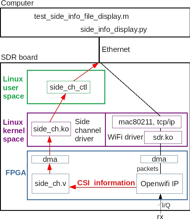
The side-channel data path. side_ch captures and DMAs to the board's processor, and side_ch_ctl forwards to a display script on your PC.
Unlike every other openwifi FPGA module, side_ch is not driven by sdr.ko. You load and unload it on demand, so it has its own module and its own tool.
Building
Prebuilt SD images already ship both side_ch.ko and side_ch_ctl, with side_ch_ctl on $PATH (see Building SD Images). The SD image can be older than your source tree, so after updating a board, rebuild both pieces from the current source rather than trusting what shipped on the image.
side_ch_ctl is a user-space tool, so it compiles directly on the board. From your host's openwifi checkout:
# on your host, copy the current source to the board:
scp -r openwifi/user_space/side_ch_ctl_src root@192.168.10.122:/root/openwifi/

# on the board, compile it and replace the binary the recipes call:
cd /root/openwifi/side_ch_ctl_src
gcc -o side_ch_ctl side_ch_ctl.c
cp side_ch_ctl /root/openwifi/side_ch_ctl
That is enough on its own when side_ch.ko's driver source, the board kernel, the FPGA image, and the device tree have not changed. Rebuild and reload side_ch.ko too when any of those changed:
# on your host (needs the adi-linux kernel source from
# prepare_kernel.sh, see Rebuilding the driver on the
# Software Development Workflow page):
cd openwifi/driver/side_ch
./make_driver.sh $XILINX_DIR $ARCH_BIT   # ARCH_BIT: 32 or 64
scp side_ch.ko root@192.168.10.122:/root/openwifi/

# on the board, reload the replacement module:
cd /root/openwifi
rmmod side_ch
insmod ./side_ch.ko
make_driver.sh must run from openwifi/driver/side_ch, exactly two levels below your checkout root, because it locates the rest of the checkout relative to its own working directory. Running it from anywhere else fails.
Replace 192.168.10.122 with your board's address (see Getting Started for the default). side_ch.ko must match the board's running kernel and the loaded FPGA design. Do not reload the module while side_ch_ctl g is running.
Loading side_ch.ko in CSI or IQ mode
The module has two parameters, and one of them silently decides which of the two capture modes you get:
| Parameter | Default | Valid | Meaning |
|---|---|---|---|
num_eq_init |
8 | 0–8 | Equalizer outputs (52 values each) appended to each CSI capture |
iq_len_init |
0 | 0, or 1–8187 | IQ samples per capture. 0 means CSI mode, anything > 0 switches to IQ mode |
insmod side_ch.ko                    # CSI mode, 8 equalizer outputs
insmod side_ch.ko num_eq_init=3      # CSI mode, 3 equalizer outputs
insmod side_ch.ko iq_len_init=8187   # IQ mode, 8187 samples per trigger
rmmod side_ch                        # unload
Set num_eq and iq_len at insmod time, not by writing registers
The driver computes how many 64-bit symbols one capture occupies from the module parameters, while registers 4 and 12 tell the FPGA the same thing. Writing those registers by hand moves the FPGA's idea of the capture size without moving the driver's, and the framing desynchronizes. Reload the module instead.
The driver clamps iq_len_init to 8187 (derived below). It does not know about small-BRAM boards, so on Zynq-7020 that clamp is too generous (see below).
What insmod leaves behind
dev_probe() arms the core with working defaults. It sets capture-everything matching (register 1 = 0x0001) and loads num_eq into register 4. In IQ mode it also enables the capture (register 3 = 1), sets a pre_trigger_len of 8190, and selects the FCS trigger (register 8 = 0). It then pulses a full reset via register 0. In CSI mode it leaves the trigger register pointing at an RSSI condition that can never fire, since CSI capture doesn't use it.
Small-BRAM boards
Zynq-7020 boards (ZedBoard, ADRV9364-Z7020, ZC702, antsdr, e310v2, antsdr_e200, sdrpi, neptunesdr, LibreSDR) build side_ch with the SIDE_CH_LESS_BRAM macro, halving the capture FIFO from 8192 to 4096 symbols. On those boards keep iq_len_init ≤ 4095, and fix the pre-trigger length yourself, because the driver's default of 8190 overshoots the smaller FIFO:
insmod side_ch.ko iq_len_init=4095
./side_ch_ctl wh11d4094
You never have to guess which build you have. Register 22 reports it:
./side_ch_ctl rh22 1 # 8192 = full build, 4096 = SIDE_CH_LESS_BRAM
Command format
side_ch_ctl takes its instructions as a single parameter string, which is one argument with no spaces and no separators between the fields. The commands are therefore hard to read until you know where the fields break. Every string is one of three actions:
./side_ch_ctl whXdY     # write register X with decimal value Y
./side_ch_ctl whXhY     # write register X with hex value Y
./side_ch_ctl rhX       # read register X
./side_ch_ctl g         # get captures, polling every 100 ms
./side_ch_ctl gN        # get captures, polling every N ms
How to read a parameter string
The fields run left to right, butted up against each other:
| # | Field | Values | Notes |
|---|---|---|---|
| 1 | Action | w write, r read, g get |
|
| 2 | Register type | h hardware, s software |
Required for w and r. Which one you pick makes no difference (see below). |
| 3 | Register index | 0 to 31, decimal |
The parser reads digits until it hits the radix letter. |
| 4 | Radix | d decimal, h hex |
Write only: how to read the value that follows. |
| 5 | Value | Write only. |
For g, everything after the g is the poll interval in milliseconds. g runs until you press Ctrl+C.
So the commands scattered through the recipes decompose like this:
| Command | Reads as |
|---|---|
rh22 |
read hardware register 22 |
wh1h4001 |
write hardware register 1, hex, 0x4001 |
wh11d4094 |
write hardware register 11, decimal, 4094 |
wh7h01ece28f |
write hardware register 7, hex, 0x01ece28f (a MAC's last 32 bits) |
g400 |
get captures every 400 ms |
Both radixes work on every register, so the choice is only about readability. The recipes use h for the bit-packed registers (1, 5) and for MAC targets (6, 7), where decimal would be unreadable, and d for plain counts like pre_trigger_len.
What the parser accepts
- Lowercase only.
WH3D987is rejected. The uppercase branches exist inside_ch_ctl.cbut are commented out. - The register index must be 0 to 31, else you get
Invalid register index (should be 0~31)!.side_ch.kodoes not re-check this, so this check is the only protection against a write past the register file. - The whole string must be 1 to 31 characters.
- A malformed
ginterval falls back to 100 ms with a warning instead of failing, so a typo likegfoopolls at the default rather than exiting. - A read needs at least 3 characters, a write at least 5 (
wh3d9is the shortest legal write).
The h/s register-type letter makes no difference
The register-type letter (h hardware, s software) is parsed and sent to the kernel, but side_ch.ko ignores it and touches the same register either way: rh20 and rs20 are identical. Use h. The distinction is vestigial.
Extra arguments
Two flags that appear in no app note:
./side_ch_ctl g -s 192.168.10.2     # send captures to this PC instead of the default
./side_ch_ctl rh20 1                # "value only": print just the number
-s sets the UDP destination. It defaults to 192.168.10.1, and the port is fixed at 4000. Any other extra argument turns on value-only mode, which drops the parse:/tx:/rx: lines and prints the bare value. That's what you want when reading a register from a script. (The 1 above is a convention, any extra argument works.)
What g does
Each poll makes one round trip. The driver reads register 20 for the number of symbols in the FIFO, rounds down to whole captures, then writes register 2 to start DMA. After waiting up to 100 ms for DMA to finish, side_ch_ctl forwards the result to your PC over UDP and prints a progress line every 64 polls:
loop 64 side info count 61
loop 128 side info count 99
The second number is your health check. If "side info count" keeps climbing, captures are flowing. If it stays at zero, nothing is triggering. Check the match configuration (register 1), and in IQ mode also check the trigger condition (register 8).
One capture is:
| Mode | Symbols per capture (64-bit each) |
|---|---|
| CSI | 2 + 56 + num_eq × 52 (the leading 2 are the timestamp and the frequency offset). With the default num_eq=8, 474 symbols (3792 bytes) |
| IQ | 1 + iq_len (the extra symbol is the timestamp) |
The IQ formula sets the 8187 limit: (8187 + 1) × 8 = 65504 bytes, which just fits in a single UDP datagram.
The FPGA only queues a capture when the FIFO has room for all of it. When room is short, the whole capture is dropped, never truncated, so polling too slowly on a busy channel costs you complete captures rather than corrupting the stream.
Register reference
These are the side_ch core's slv_regN in side_ch.v. Several registers mean different things in CSI mode and IQ mode, because the two modes reuse the same bits. Registers 13 to 18 and 23 to 25 are not connected in the current build.
Configuration
| reg | Mode | Meaning |
|---|---|---|
| 0 | both | Reset, per bit, write 1 to hold: bit0 the DMA-to-PS stream, bit2 the capture FSM. (bit1 is an unused reset of the AXI-Stream slave interface (S-AXIS).) |
| 1 | both | Config. bits1-0 start mode: 1 = normal (transfer starts when reg 2 is written), 0 = S-AXIS loopback, 2 = external trigger, 3 = off. bit4 endless mode. bit12 FC match, bit13 addr1 match, bit14 addr2 match. |
| 2 | both | Symbol count for the next DMA transfer. Writing it starts the transfer: that's what "start mode 1" means. side_ch.ko writes it on every g poll, so you never touch it. |
| 3 | IQ | bit0 enables IQ capture. bits5-4 pick what each sample carries: 0 = antenna 0 IQ + AGC gain + status, 1 = antenna 0 and antenna 1 IQ (dual-antenna capture), 2 = antenna 0 IQ + AGC gain + a status word with tx_control_state and Frame Control instead. |
| 4 | CSI | bits3-0 num_eq (0–8). Set via num_eq_init, not here. |
| 4 | IQ | bit4 drops the "packet needs ACK" requirement from the TX triggers (for trigger 3 it adds the requirement instead, see the trigger notes). bits2-0 are a PPDU-format target reserved for 11ax and unused today. |
| 5 | CSI | bits15-0 the Frame Control match target. |
| 5 | IQ | bit0 free-run. bits2-1 IQ source: 0 = received IQ (AD9361), 1 = openofdm_tx output, 2 or 3 = tx_intf output. bits7-4 tx_control_state target. bits9-8 phy_type target (0 legacy, 1 HT, 2 HE). |
| 6 | both | addr1 (destination) match target: the last 32 bits of the MAC. |
| 7 | both | addr2 (source) match target, last 32 bits. Also the addr2 target used by the event counters. |
| 8 | IQ | bits4-0 trigger select, 0–31. See the trigger table. |
| 9 | IQ | bits15-0 threshold, doing double duty: RSSI in rssi_half_db (bits10-0, read as a signed value, so keep it ≤ 1023) for triggers 10/11 and the rssi_above_th counter, or antenna 1's in-phase amplitude for triggers 28–31. |
| 10 | IQ | bits6-0 AGC gain threshold (0–127), for triggers 14/15. |
| 11 | IQ | bits13-0 pre_trigger_len: how many samples before the trigger are kept. Max 8190, or 4094 on small-BRAM boards. |
| 12 | IQ | bits13-0 iq_len. Set via iq_len_init, not here. |
| 19 | both | Counter event-source select: bits 0, 4, 8, 12, 16, 20 choose the source for registers 26–31 respectively. |
Register 3 does not choose where the IQ comes from
Its bit 0 switches the core between CSI and IQ mode, and bits 5-4 choose what gets packed into each 64-bit word (including whether antenna 1's samples ride along). The tap point (off the air, or your own transmit) is register 5 bits 2-1, and nothing in register 3 touches it. The upstream IQ app note annotates wh3h01 with "configure the IQ data source." The command only works in the quick start because register 5 is already 0 (received IQ). Register 3 does not set the source.
Read-only
| reg | Meaning |
|---|---|
| 20 | Symbols waiting in the capture FIFO. |
| 21 | Max symbols per UDP datagram: 8188, or 4096 on a small-BRAM build. |
| 22 | FIFO depth: 8192 = full build, 4096 = SIDE_CH_LESS_BRAM (see Small-BRAM boards). |
| 26–31 | Event counters (see below). Writing any value clears one. |
Trigger reference (register 8)
In IQ mode, register 8 picks the one condition that fires a capture. ./side_ch_ctl wh8dY:
| Y | Fires when |
|---|---|
| 0 | Decoding finishes with FCS pass or fail. With reg 5 bit0 set, it free-runs instead. |
| 1 | Decoding finishes with FCS pass |
| 2 | Decoding finishes with FCS fail |
| 3 | The first IQ of a transmitted packet reaches the DAC, and it isn't a retransmission |
| 4 | SIGNAL-field (PHY header) checksum passes |
| 5 | SIGNAL-field (PHY header) checksum fails |
| 6 | SIGNAL field checked, and the packet is HT |
| 7 | SIGNAL field checked, and the packet is non-HT |
| 8 | Long preamble detected |
| 9 | Short preamble detected |
| 10 | RSSI crosses above the reg 9 threshold |
| 11 | RSSI crosses below the reg 9 threshold |
| 12 | AGC goes from lock to unlock |
| 13 | AGC goes from unlock to lock |
| 14 | AGC gain crosses above the reg 10 threshold |
| 15 | AGC gain crosses below the reg 10 threshold |
| 16 | tx_control_state changes to the reg 5 bits7-4 target |
| 17 | phy_tx_done |
| 18 | TX baseband starts (rising edge of tx_bb_is_ongoing) |
| 19 | TX baseband stops (falling edge of tx_bb_is_ongoing) |
| 20 | TX RF starts (rising edge of tx_rf_is_ongoing) |
| 21 | TX RF stops (falling edge of tx_rf_is_ongoing) |
| 22 | TX starts (phy_tx_started), for a packet that needs an ACK |
| 23 | TX finishes (phy_tx_done), for a packet that needs an ACK |
| 24 | Both the tx_control_state and phy_type targets in reg 5 are hit |
| 25 | addr2 seen, subject to the match bits in reg 1 |
| 26 | TX RF starts, for a packet that needs an ACK |
| 27 | TX RF stops, for a packet that needs an ACK |
| 28 | The absolute value of antenna 1's in-phase samples exceeds the reg 9 threshold while TX baseband is ongoing (collision capture) |
| 29 | The absolute value of antenna 1's in-phase samples exceeds the reg 9 threshold while TX RF is ongoing (collision capture) |
| 30 | TX starts while antenna 1's in-phase amplitude exceeds the threshold |
| 31 | As 30, for a packet that needs an ACK |
Before you rely on this table:
- Free-run is trigger 0 only.
wh8d0alone still waits for a decode. Pair it withwh5d1to stream continuously. - Trigger 25 reinterprets the match bits. Register 1's bits 13 and 14 still mean addr1 and addr2 match, but bit12 selects a phy_type match here rather than a Frame Control match.
- Reg 4 bit4 works the other way around for trigger 3. For triggers 22, 23, 26, 27, and 31 the bit removes the needs-ACK requirement, as its name (
disable_tx_pkt_need_ack_check) suggests. Trigger 3 defaults to firing on every transmission, and setting the bit adds the requirement, narrowing the capture to packets that expect an ACK. - Capturing your own signal off the air needs the receiver unmuted. openwifi mutes the RX baseband during its own transmission, so a TX trigger with IQ source 0 (received IQ) records silence. Unmute it first:
./sdrctl dev sdr0 set reg xpu 1 1.
Event counters (registers 26–31)
Once side_ch.ko is loaded, the FPGA counts PHY RX and TX events in either capture mode. Each counter has two selectable sources, chosen by a bit in register 19:
| reg | reg 19 bit | Source when 0 | Source when 1 |
|---|---|---|---|
| 26 | bit0 | short preamble detected | phy_tx_start |
| 27 | bit4 | long preamble detected | phy_tx_done |
| 28 | bit8 | PHY header strobe | RSSI above threshold |
| 29 | bit12 | PHY header valid | AGC gain change |
| 30 | bit16 | data packet, decoded, addr2 matched | AGC lock |
| 31 | bit20 | data packet, decoded with good FCS, addr2 matched | TX packet needs ACK |
The counters are 16 bits wide and wrap silently, so clear the ones you use at the start of a measurement window.
./side_ch_ctl wh7h01ece28f   # addr2 target: the FCS counters always require an addr2 match
./side_ch_ctl wh9d500        # threshold for the "RSSI above" event
./side_ch_ctl rh31 1         # read counter 31
./side_ch_ctl wh31d0         # write any value to clear it
Registers 30 and 31 read together give you a per-peer PER: 31 counts the good ones, 30 counts every decode attempt. For a proper rssi_above_th threshold, take the value from auto_lbt_th in openwifi_rf_rx_update_after_tuning() in sdr.c. The openofdm_rx watchdog has a separate set of counters reached through sdrctl instead. Both are covered on the Research Features page.
Common problems
"side info count" stays at 0
Nothing is matching or triggering. In CSI mode, reset the filter with wh1h0001 to capture every packet and confirm the channel is busy. In IQ mode, also check register 8, since a trigger like "AGC gain crosses a threshold" may never happen.
Captures arrive but the plots are garbage
num_eq (CSI) or iq_len (IQ) is out of step somewhere. The value has to match in three places: the insmod parameter, the Python script's argument, and the num_eq or iq_len variable in the MATLAB script.
A reloaded module still carries the last session's settings
Reloading side_ch.ko does not return the core to a clean state. dev_probe() writes only registers 0, 1, 3, 4, 8, 11, and 12, and it writes registers 3, 11, and 12 only in IQ mode. Registers 5, 6, 7, 9, 10, and 19 keep whatever you last put there. The reset it pulses through register 0 drives the capture FSM, not the register file, which clears only when the FPGA is reconfigured. This causes two problems:
- A leftover
wh5h4from a loopback test still tapstx_intfafter the reload, so the IQ quick start silently captures your own transmit instead of the air. Register 5 needs no enabling bit, so nothing else hides the mistake. - Going from IQ mode back to CSI mode by reloading with no
iq_len_initshould leave register 3 bit 0 still set, because the driver only writes that register wheniq_len_init > 0. The FPGA would then stay in IQ mode while the driver frames for CSI. This follows from the source but is not yet confirmed on hardware (see the suspected upstream bug).
Write the stale registers back by hand (wh5d0, wh3d0), or reload the bitstream with ./wgd.sh for a guaranteed clean state. On a Buildroot image plain ./wgd.sh keeps the FPGA that U-Boot loaded, so force the reprogram with OPENWIFI_RELOAD_FPGA=1 ./wgd.sh.
Nothing reaches the PC
The stream is UDP to port 4000 at 192.168.10.1 unless you passed -s. Run the display script on the PC itself, not over ssh, and check that the board can reach that address.
IQ capture is truncated or empty on a Zynq-7020 board
The FIFO is half-size there. Confirm with rh22, keep iq_len_init ≤ 4095, and set wh11d4094.
A suspected upstream bug (unverified)
This was found by reading the openwifi source, not by testing on a running board, and it is not reported upstream. Treat it as unconfirmed. Check it before relying on it, and raise an issue against open-sdr/openwifi if it holds.
Register 3 survives a reload back into CSI mode
dev_probe() in side_ch.c writes register 3 only inside if (iq_len_init > 0). Nothing else clears the AXI register file, since register 0's reset bits drive the capture FSM and not the registers. So IQ mode should persist across an insmod that omits iq_len_init, leaving the FPGA in IQ mode while the driver frames captures for CSI.
To confirm: run IQ mode, then rmmod side_ch, insmod side_ch.ko, and rh3. If bit 0 is still set, the bug is real and the CSI display should show garbage until you write wh3d0 or reload the bitstream.