Supported Boards and Hardware
openwifi runs on Xilinx Zynq-7000 and Zynq UltraScale+ (MPSoC) boards. Nearly all pair the SoC with an Analog Devices AD9361-family RF front end, either an FMCOMMS2/3/4 card or an integrated equivalent. The RFSoC4x2 instead uses integrated RF data converters, and the driver treats it as a separate hardware type.
The board_name is the key identifier
Every board has a short board_name used identically across all repos: openwifi-hw/boards/<board_name>/, openwifi-hw-img/boards/<board_name>/sdk/, and openwifi/kernel_boot/boards/<board_name>/. Set export BOARD_NAME=<board_name> before running any build script. See Repositories.
The board matrix
board_name |
Hardware | SoC | Vivado license required? | Notes |
|---|---|---|---|---|
zc706_fmcs2 |
Xilinx ZC706 + AD-FMCOMMS2/3/4 | Zynq-7045 | Yes | High-end development board, 100 or 200 MHz baseband clock |
zed_fmcs2 |
ZedBoard (Avnet, Digilent) + AD-FMCOMMS2/3/4 | Zynq-7020 | No | The classic reference board, fully tested |
zc702_fmcs2 |
Xilinx ZC702 + AD-FMCOMMS2/3/4 | Zynq-7020 | No | |
zcu102_fmcs2 |
Xilinx ZCU102 + AD-FMCOMMS2/3/4 | Zynq UltraScale+ (64-bit) | Yes | The only 64-bit board with public images, needs ATF and PMUFW boot stages, 240 or 100 MHz baseband clock |
adrv9364z7020 |
ADRV9364-Z7020 SoM + ADRV1CRR-BOB breakout carrier | Zynq-7020 | No | Integrated AD9364 (one RX and one TX channel) |
adrv9361z7035 |
ADRV9361-Z7035 SoM + ADRV1CRR-BOB/FMC | Zynq-7035 | Yes | AD9361 (2×2 capable), very low TX power at 5 GHz, 100 or 200 MHz baseband clock |
antsdr |
MicroPhase enhanced ADALM-Pluto | Zynq-7020 | No | See caveat below |
e310v2 |
MicroPhase "new antsdr" (E310 v2) | Zynq-7020 | No | Adds GPS, an external reference input, and a VCXO |
antsdr_e200 |
MicroPhase enhanced ADALM-Pluto (smaller and cheaper) | Zynq-7020 | No | Ethernet on PL side |
sdrpi |
HexSDR, Raspberry-Pi-form-factor SDR | Zynq-7020 | No | GPS and many I/O pins |
neptunesdr |
Low-cost Zynq-7020 + AD9361 board | Zynq-7020 | No | Unofficial, community supported |
rfsoc4x2 |
AMD RFSoC4x2 | Zynq UltraScale+ RFSoC | Yes | Driver support only. No public FPGA project, boot files, or bitstream. See the note below. |
LibreSDR |
Low-cost Zynq-7020 + AD9361 board | Zynq-7020 | No | Unofficial, external repo openwifi-libresdr |
The Vivado license column only matters if you rebuild the FPGA from source. The prebuilt bitstreams run on any board with no license. Boards on the Zynq-7020 qualify for the free Vivado tier.
The RFSoC4x2 has driver support only
The openwifi-hw README lists the RFSoC4x2, and the driver detects it by its TI LMK04828 clock chip (see The Linux Driver). However, the master branches have no rfsoc4x2 board project in openwifi-hw and no boot files in openwifi/kernel_boot/boards/. openwifi-hw-img has no prebuilt bitstream for it either. This means you cannot build or flash an RFSoC4x2 image from the public repositories.
Boot files for the ADRV9361-Z7035 on the FMC carrier
kernel_boot/boards/adrv9361z7035_fmc/ holds a prebuilt device tree for the ADRV1CRR-FMC carrier. Compared with the adrv9361z7035 tree, it adds the carrier's AD9517 clock chip and enables a second Ethernet port. No build script refers to it, and it has no overlay in overlays/, so construct_device_tree.sh cannot regenerate it. To use it, copy its devicetree.dtb to the BOOT partition in place of the default one.
Small-FPGA (Zynq-7020) boards have reduced buffers
Boards built on the Zynq-7020 (ZedBoard, ADRV9364-Z7020, ZC702, antsdr, e310v2, antsdr_e200, sdrpi, neptunesdr, LibreSDR) have less block RAM. The side_ch capture engine shrinks its DMA buffer on these boards (SIDE_CH_LESS_BRAM), so IQ and CSI captures have lower length limits. iq_len_init can be at most 4095 and pre_trigger_len at most 4094. The larger FPGAs allow 8187 and 8190. The relevant Research Features recipes call this out.
No hardware? Use the testbed
If you have no board at all, the imec w-iLab.t testbed offers remote access to openwifi-ready boards (and supports JTAG boot instead of SD-card boot). It is the fastest way to try openwifi and to develop against real hardware you don't own.
Community boards from MicroPhase and HexSDR
ANTSDR (MicroPhase)
An enhanced ADALM-Pluto built on a Zynq-7020 and an AD936x. It works as a generic SDR (PlutoSDR or FMCOMMS class) and as an openwifi platform.
ANTSDR RF-switch frequency limitation
The stock ANTSDR RF front-end switch is hardcoded to the high band and only passes 3 to 6 GHz, so frequencies below 3 GHz are blocked. Upstream lists RF-switch control in the device tree as future work, which would let the switch follow the tuned frequency. Until then, plan to test ANTSDR in the 5 GHz band. (openwifi/kernel_boot/boards/antsdr/notes.md.)
ANTSDR-E200 (MicroPhase)
A smaller, cheaper version of the ANTSDR-E310. Its network port is on the PL (FPGA fabric) side instead of the Zynq PS side to carry high-rate traffic. Above a 20 Msps baseband sample rate, the Ethernet link carries about 80 MB/s, which would saturate the CPU through the PS-side Zynq GEM controller. The board retains both paths: PL-side Ethernet supports the UHD driver through MicroPhase's separate antsdr_uhd project, while IIO-based SDR drivers still use the PS-side controller.

ANTSDR-E310 v2 (MicroPhase)
An upgraded E310 aimed at LTE, GSM, and Wi-Fi experiments. Compared with the original E310, it has improved RF performance, an onboard GPS module, an external 10 MHz and PPS reference input, and a VCXO. A DAC steers the VCXO against the external reference for a more accurate, stable clock, which matters for time synchronization and TSN work. Like the E200, it puts Ethernet on the PL side for UHD-driver-class throughput.
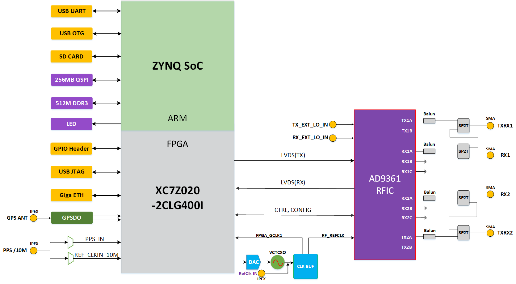
SDRPi (HexSDR)
A Zynq-7020 + AD936x SDR in a Raspberry-Pi form factor.
| Spec | Value |
|---|---|
| SoC | Zynq XC7Z020-CLG400 |
| Memory | 1 GB PS-side DDR3 |
| Ethernet | Two 1 Gb ports (one PS, one PL) |
| USB | USB OTG, dual USB-UART (PS + PL) |
| Debug | Onboard USB-to-JTAG debugger |
| Boot media | microSD + bootable QSPI flash |
| GPIO | 27 PL-bank 3.3 V pins for connecting other modules |
| RF front end | FMCOMMS3-based, with an added RF amplifier |
| Timing | u-blox M8T GPS module and a 40 MHz VCXO |
Board bring-up quirks worth knowing up front
- ADRV9361-Z7035 low 5 GHz TX power. Keep nodes close (or plan for attenuation) when testing this board at 5 GHz. This is called out in nearly every Operating Modes walkthrough.
- ZCU102 differs from every other board. It is the only 64-bit (Zynq UltraScale+) board with public images. It uses a different boot chain, with ARM Trusted Firmware BL31 and PMU firmware built by
build_zynqmp_boot_bin.sh. Its device tree issystem.dtsinstead ofdevicetree.dts. It can also hit SD card, RTC, and SODIMM module issues (see Troubleshooting). - neptunesdr sometimes shows an
EXT4-fs erroron first boot. Re-flash with a different imaging tool. - CH341-based UART adapters (antsdr_e200 and others) may need
sudo apt remove brlttybefore the console device appears.
The baseband clock per board
The FPGA baseband clock is set by NUM_CLK_PER_US at the top of openwifi-hw/boards/openwifi.tcl (default 100 MHz). Available options depend on the board's timing closure:
| Board | Baseband clock options |
|---|---|
zcu102_fmcs2 |
240 or 100 MHz |
zc706_fmcs2, adrv9361z7035 |
100 or 200 MHz |
| all other boards | 100 MHz |
Changing it requires re-running openwifi.tcl to regenerate the project (see FPGA Development → Changing the baseband clock). The baseband clock is itself derived from the AD9361 sample clock so RF and baseband never drift. See Architecture.
GPIO and LED map for visual debugging
openwifi-hw routes several real-time FPGA status signals to board LEDs and PMOD test points. This makes it much easier to probe the TX, RX, and CSMA state machines on hardware. Some LEDs use a flip signal, which toggles on each event pulse so the LED visibly flashes. Others are raw and follow the live signal level directly.
On the ZCU102, for example, the LEDs map to:
| LED | Signal (source) | Meaning |
|---|---|---|
| LED0 | clk_wiz_0 locked (raw) |
RF–baseband clock is locked |
| LED1 | tx_itrpt_led (tx_intf.v) |
Interrupt raised after the FPGA sent a packet |
| LED2 | tx_end_led (tx_intf.v) |
openofdm_tx finished generating IQ for a packet |
| LED3 | fcs_ok_led (rx_intf.v) |
openofdm_rx reported CRC-OK for a packet |
| LED4 | demod_is_ongoing_led (xpu.v) |
Receiver is actively demodulating |
The ZCU102 also has raw PMOD test points for tx_bb_is_ongoing, tx_rf_is_ongoing, and demod_is_ongoing. These let you watch TX and RX turnaround timing directly on a scope. The ADRV9361-Z7035 map adds cycle_start, sig_valid, and phy_tx_started LEDs. It also has four slice_en[0..3] lines that show which of the four TX queues are gated open. The full per-board table is in openwifi-hw/gpio_led.md.
To build with the ILA debug cores that complement these LEDs, see FPGA Development → Debugging on hardware.